Look a little closer
See the mechanism
Two strokes, opposite valve states
Read every step
- Press. The piston reduces chamber volume. Pressure closes the inlet and opens the outlet, sending the chamber contents toward the nozzle.
- Release. The spring lifts the piston. Chamber pressure falls: the outlet closes and the inlet opens, admitting liquid through the dip tube.
Illustrative liquid-pump circuit, not a product cutaway or to scale. Valve positions and spring geometry are simplified. Initial strokes prime an air-filled pump. A separate bottle vent admits replacement air. Foaming pumps add another circuit.
Diagram basis: US11389814B1: downstroke and upstroke.
Sources: Armin Arminak / USPTO; document hosted by Google Patents · Saint-Gobain Calmar, S.A. / European Patent Office · James M. Tuyls, Thomas R. Hecht and Juha K. Salmela / USPTO; document hosted by Google Patents
The bottle is a supply, not the pump chamber
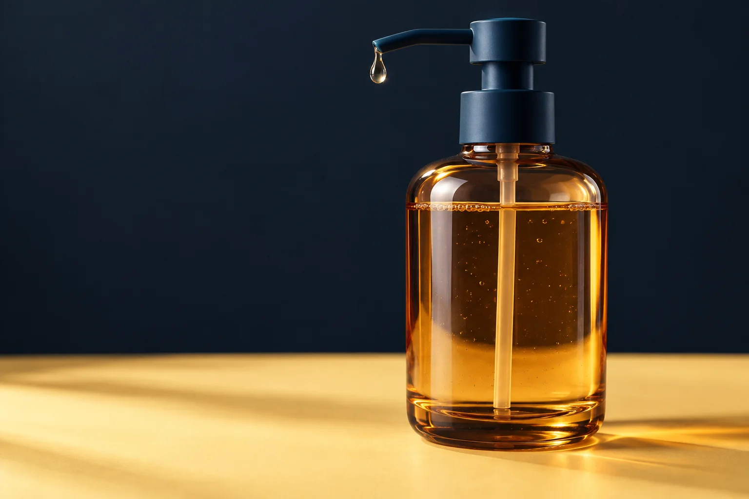
The small chamber inside the dispenser is where the pressure changes occur. A dip tube connects it to liquid in the container; another route leads toward the nozzle. Patent US11389814B1 documents a hand-operated dispenser with a piston, a return spring and lower and upper check valves.
Its particular construction uses a plastic spring and a flexible upper valve integrated with the piston. Those details are examples, not a parts list for every soap bottle. The shared idea worth following is the sequence of chamber filling and emptying.
Sources: Armin Arminak / USPTO; document hosted by Google Patents
Follow one complete cycle
Once the chamber contains liquid, pressing the head moves the piston and increases pressure. The inlet valve closes; the outlet route opens. Liquid leaves through the dispensing passage instead of being pushed straight back into the bottle.
On release, the spring returns the piston. The outlet closes and the inlet opens as chamber pressure falls, admitting another charge of liquid. A Calmar patent describes this variable-volume chamber cycle, with an added brief product-retraction step to discourage drips. That extra feature is omitted from our basic diagram.
Why two routes need gates
A second patent, US8152029B2, describes inlet and outlet check valves that permit flow predominantly in their respective directions. It concerns a condiment dispenser with a deliberately different piston clearance and bypass, rather than an ordinary soap pump. It is useful evidence that a pump's exact internal layout depends on the product it must move.
Without directional control, changing the chamber volume would not by itself guarantee delivery through the spout. In the simplified model, the valves decide which route is available during each stroke. Think of them as pressure-operated gates; your finger does not individually command each valve.
Sources: James M. Tuyls, Thomas R. Hecht and Juha K. Salmela / USPTO; document hosted by Google Patents
Why a new pump may need several presses
Before liquid reaches the chamber, a stroke can move air instead. US11389814B1 describes this priming sequence: air exits on a downstroke and liquid is drawn in on the return. A first press with no soap is therefore compatible with the mechanism still filling.
When reading the diagram, pause at each state and ask two questions: which valve is open, and where can the contents go? That makes the explanation easier to follow than watching the head alone. It also keeps refill separate from dispensing, although both belong to the same press-and-release cycle.
Sources: Armin Arminak / USPTO; document hosted by Google Patents
The thing to remember
A changing chamber volume moves the contents; one-way valves turn that movement into useful delivery.
What this example leaves out
This is a conceptual liquid-pump cycle, not a teardown of a named soap dispenser. Foam pumps mix air and liquid using additional arrangements. Valve shapes, springs, seals, venting and locking mechanisms vary; the diagram omits those construction details.
Sources & further reading
Source access dates are listed below. Manufacturer descriptions and patents support the specific constructions described, not every product.
- US11389814B1 — All plastic hand pump with a piston having an integrated check valve ↗
Armin Arminak / USPTO; document hosted by Google Patents · Retrieved 2026-10-14 · Actuator, piston, dip tube, lower and upper check valves, plastic return spring; press/release cycle and dry-pump priming sequence.
A disclosed all-plastic hand-operated liquid pump, not a teardown or market prevalence study. Patent also discusses spray configurations; the article extracts the liquid displacement principle and does not equate every nozzle with a soap spout. Recycling and rust claims omitted. - EP1136135A2 — Fluid pump dispenser having product retraction feature ↗
Saint-Gobain Calmar, S.A. / European Patent Office · Retrieved 2026-10-14 · Variable-volume chamber and manual pressure/return strokes; valve-controlled inlet and discharge; brief return-stroke product retraction followed by refill, especially paragraphs 0015–0024.
Specific anti-drip embodiment confirms the broader chamber-volume principle but adds timing absent from the conceptual diagram. No exact patent assembly is reproduced; product retraction is explicitly distinguished from the simple cycle. - US8152029B2 — Pump dispenser with bypass back flow ↗
James M. Tuyls, Thomas R. Hecht and Juha K. Salmela / USPTO; document hosted by Google Patents · Retrieved 2026-10-14 · One-way inlet and outlet valves; spring-biased piston; deliberately different clearance and bypass geometry for condiment dispensing.
This is a condiment pump, not evidence of the exact construction of an ordinary soap pump. Used only as a stated comparison showing why internal arrangements vary. Does not supply a soap-pump seal specification.