Look a little closer
See the mechanism
The die supports the edge that stays
Read the diagram steps
Before the cut. The handle pivots while its short contact presses a vertically guided punch. The sheet spans a matching opening in the supporting die.
Cutter through the die. The cutter enters the die opening and separates a disk. The die supports the surrounding paper; the spring withdraws the cutter after the stroke.
Functional section; punch/die gap is exaggerated. Lever arrangement follows US4656907; no exact inclined cutter profile or sheet capacity is claimed.
Diagram basis: US4656907: handle, guided pins and die.
Sources: United States Patent Office / Google Patents · United States Patent and Trademark Office / Google Patents
A hole needs somewhere for the disk to go
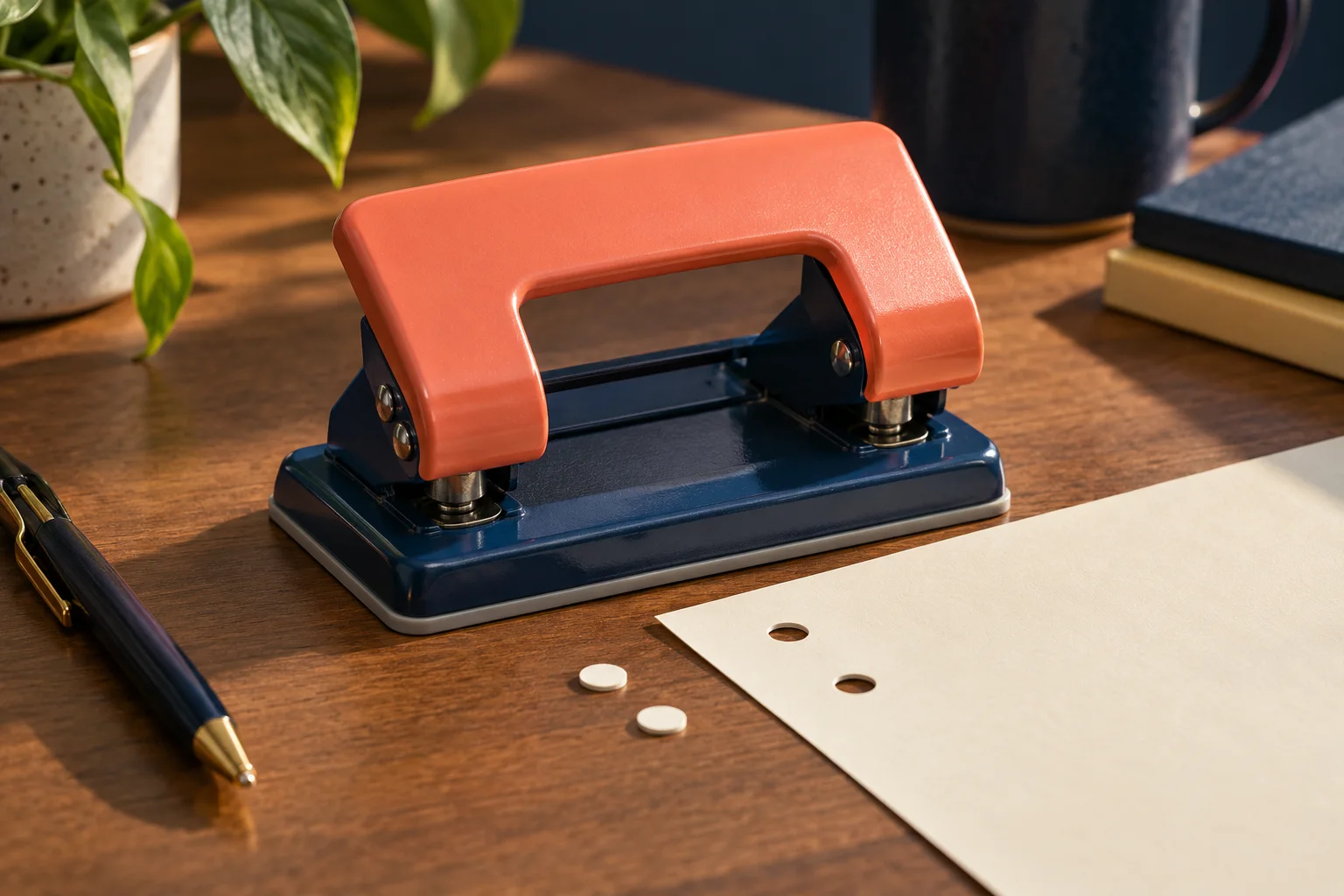
Press a blunt object onto unsupported paper and much of the sheet can move with it. In a punch, paper outside the cutting circle rests on the die. The cutter enters the opening instead of crushing the sheet against a solid floor.
The separated disk, often called a chad, passes below the sheet. The hole is the boundary left behind. The cutter and die therefore need to line up: the punch moves through an opening already positioned beneath it.
The handle turns; the cutter travels straight
The long handle gives the hand a larger turning arm than the short distance at which it presses on the punch mechanism. That geometry trades handle travel for a larger downward force. Guides keep the cutter's movement straight even though the handle swings through an arc.
In U.S. Patent 4,656,907, a handle presses a bar that drives several punch pins together. Springs raise the pins again. A two-hole desk punch can apply the same basic force path at two positions, without requiring the hand to press directly above each cutter.
Sources: United States Patent and Trademark Office / Google Patents
The whole circle needn't cut at once
The edge can reach different parts of the circle at different moments. U.S. Patent 3,087,367 describes an inclined, concave cutter face: one point reaches the paper first, and the cut progresses around the rim. That is one documented cutter shape, rather than the bottom profile of every paper punch.
After the stroke, the spring withdraws the cutter and reopens the paper slot. Cutting and resetting are separate movements.
Sources: United States Patent Office / Google Patents · United States Patent and Trademark Office / Google Patents
The thing to remember
The lever supplies force, but the clean circle comes from a guided cutter passing the supported edge of a matching die.
What this example leaves out
This describes a lever-driven paper punch. Cutter profiles, die clearances, waste storage and sheet capacities vary; the patent examples establish particular mechanisms, not universal dimensions.
Sources & further reading
Source access dates are listed below. Manufacturer descriptions and patents support the specific constructions described, not every product.
- US3087367A — Self sustaining paper punch frame assembly ↗
United States Patent Office / Google Patents · Retrieved 2026-10-18 · Guided punch, aligned paper slot/die, spring return; inclined concave cutter gives progressive shearing. Description paragraphs beginning 'The engagement of the tongue', 'A spring 31', 'The bottom of the punch', and 'In the operation'.
Actual HTML description read; particular inclined and grooved cutter and frame design. No claim that every desk punch has this cutter profile or specified clearance. - US4656907A — Paper punch ↗
United States Patent and Trademark Office / Google Patents · Retrieved 2026-10-18 · Handle drives punch bar and pins against return springs; die holes aligned with pins. Claim 8 and description of handle/bar/pin assembly.
Actual HTML read after /en route returned Internal Error. Particular multi-pin lever example; basic lever mechanical-advantage explanation is qualitative analysis, not measured force.