
Look a little closer
See the mechanism
A worm changes the jaw gap
Read the diagram
The fixed jaw belongs to the wrench body. The movable jaw follows a guide, and its toothed rack engages the rotating worm. Turning the worm shifts the rack and jaw along the guide; reversing the turn reverses that adjustment. The worm rotates in place instead of sliding with the jaw.
Original functional front section, not a manufactured tooth/helix drawing. Opposed straight arrows indicate the two possible jaw directions; the loop denotes reversible worm rotation without assigning a measured turn-to-travel ratio. The cited patent’s added axial-release lever is omitted. No universal self-locking or torque rating.
Diagram basis: US5048380A: conventional worm/rack and jaw guide description.
Sources: United States patent publication via Google Patents · Bahco
The wheel meshes with a row of teeth
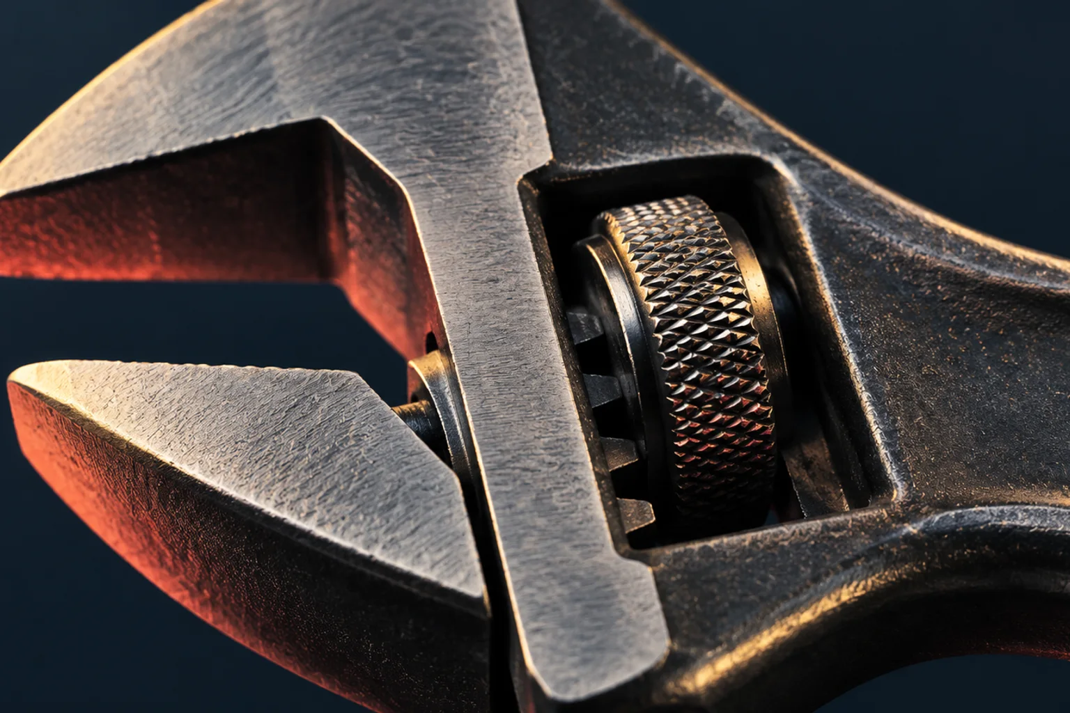
The wheel is often called the worm or adjusting knurl. Its helical thread meets a rack: a straight row of teeth on the movable jaw's stem. As the worm turns, its contacting thread surfaces push the rack along.
US5048380A describes this worm-and-rack arrangement as the conventional starting point for its wrench design. The two parts convert a rotation your thumb can make in a small space into a controlled change in jaw opening.
Sources: United States patent publication via Google Patents
The guide decides where the jaw can go
The jaw's stem slides in the wrench head. That constraint matters as much as the teeth: it allows travel along the opening direction while preventing the jaw from simply turning with the worm. Turn the adjuster the other way and the contacting thread drives the rack back.
The fixed jaw stays attached to the head while the other jaw moves along its guide. Together, the guided stem and threaded adjuster change the gap between the gripping faces without changing their basic orientation.
Sources: United States patent publication via Google Patents
Adjustment is separate from turning the fastener
The wheel sets the gap between the jaws. The long handle is the lever used when the wrench turns a mating fastener. These movements have different purposes: changing jaw position and rotating the workpiece.
Sources: Bahco · United States patent publication via Google Patents
The thing to remember
A worm thread drives a straight rack, and a guide turns that contact into linear jaw travel. The wheel sets the opening; the handle turns the work.
What this example leaves out
This selects a conventional worm-adjusted sliding jaw. It does not show the patent's extra release lever or establish universal self-locking, permissible torque, fit or safe tool use.
Sources & further reading
Source access dates are listed below. Manufacturer descriptions and patents support the specific constructions described, not every product.
- Adjustable wrench — US5048380A ↗
United States patent publication via Google Patents · Retrieved 2026-10-16 · Conventional worm meshing rack on sliding jaw converts rotation to reciprocal travel relative to fixed jaw; proposed lever is additional mechanism.
Background and description on worm/rack and groove read. Extra axially movable shaft/release lever omitted; no universal self-locking or safe torque inference. - Spare Knurl, Pin & Spring for Central Nut Adjustable Wrenches ↗
Bahco · Retrieved 2026-10-16 · Maker identifies adjusting knurl/pin/spring as distinct replaceable parts for named central-nut wrench families.
Product title and part-family list read. No exploded diagram inspected; exact helix/guide geometry still requires original figure review against mechanism.