
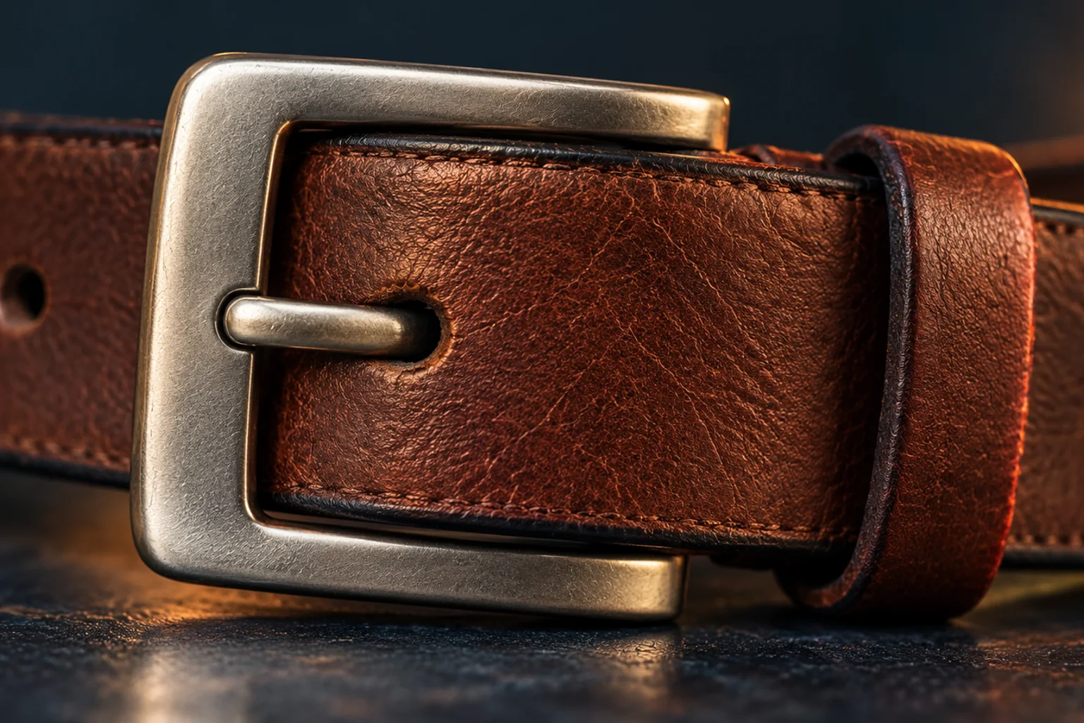
Look a little closer
See the mechanism
A pin and a frame carry the strap tension
Read the diagram
A selected hole in the free strap bears against the prong. The prong pivots on one side of the frame and its tip is supported by the opposite frame bar. The fixed strap end is attached at the hinge side. The side inset shows the free strap entering below the opposite bar and bending through the frame; the hole lets the prong cross the strap.
Original top and side principle views; the side gap marks the enlarged selected hole. They share function rather than scale or exact projection. The coral prong reaches the opposite bar. No extra stopper, friction-only locking, special wire-frame patent construction or restraint rating is implied.
Diagram basis: EP2896311A1: conventional frame and prong in Background, Figs. 1–3.
Sources: European patent publication via Google Patents · United States patent publication via Google Patents
The fixed end and the adjustable end meet differently
One end of the belt attaches to the buckle's frame. The free end passes through the frame and presents a row of possible holes. The hinged prong enters one selected hole, making the adjustment discrete rather than continuously sliding.
In the conventional arrangement described in EP2896311A1, the prong hinges on one side of the frame and its tip rests against the opposite side. The hole selected along the strap determines how much of the free end remains inside the loop.
The hole catches the prong, and the frame supports it
When tension acts along the belt, the material around the selected hole bears on the prong. The prong's connection to the frame and its opposite-side contact resist that movement. The strap cannot simply slide past while the prong still crosses its hole; the material and the metal are physically in each other's way.
US847795A likewise describes a single tongue entering an opening in a leather strap. The strap, prong and frame form a connected load path. That engagement holds the adjustment even though the strap is not squeezed between a pair of smooth plates.
Ratchet belts and friction buckles hold through other contacts. Their adjustable ends do not become this mechanism simply because the front plate looks similar. Follow the hidden route of the strap and the part that stops it moving.
Sources: European patent publication via Google Patents · United States patent publication via Google Patents
The thing to remember
The selected hole bears on a prong supported by the frame. That physical engagement holds the adjustment.
What this example leaves out
This selects a conventional hinged-prong clothing buckle, without the patents' added stopper or special frame details. Friction, ratchet and safety-restraint buckles differ. No repair or load certification is implied.
Sources & further reading
Source access dates are listed below. Manufacturer descriptions and patents support the specific constructions described, not every product.
- Belt buckle — EP2896311A1 ↗
European patent publication via Google Patents · Retrieved 2026-10-16 · Conventional prior-art frame: fixed strap end, prong hinged at one side, selected hole and opposite-frame support.
Actual backgroundFIGS1–3 explanation lines185–190 read. Proposed stopper absent from selected mechanism; no hybrid with patentnew variant or safety-restraint load claim. - Buckle — US847795A ↗
United States patent publication via Google Patents · Retrieved 2026-10-16 · Single tongue for opening in leather strap and supporting frame relationship.
Actual description and FIG7 single-leather-strap-prong explanation read. Special paired prongs, wound-wire bearing coils and frame shape not generalized.